
An E2E Azure Sphere project in the area of Smart Retail (RFID RC522, AVNet MT3620 SK, Izokee Display)

Smart Retail with the AVNet MT3620 Starter Kit and an NFC scanner
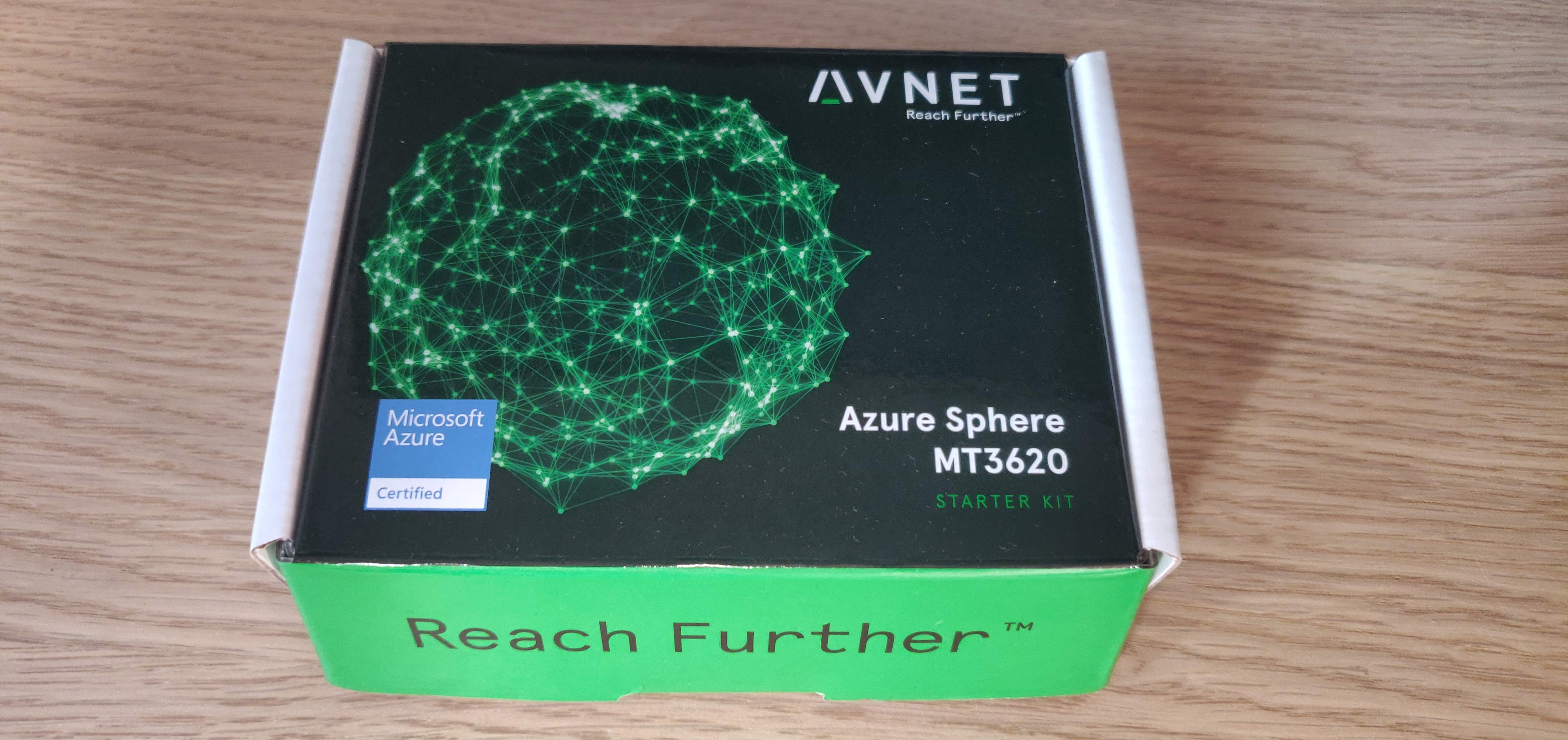
Avnet just released an MT3620 Azure Sphere Development Kit with a contest related to it.
Project Description
Title: How IoT can play a secure role in the world of Smart Retail
Description: In retail the most important thing while walking through the store is the labels displaying the price of an item. With this project I want to display how you can utilize small form factor devices to dynamically update these prices from cloud to edge. I want to demonstrate this through an LCD display that displays the item name and price. Once we then hold and RFID tag in front of an RFID Scanner it will pull the information from its local database. When we then perform a Twin Update, we will change this local database information and re-scan the tag to demonstrate this. With this we want to demonstrate the following technolgies: IoT Twins, Azure IoT Hub, IoT Edge, RFID Scanner, OLED Screens, SPI connection and I2C connection.
Breaking this up into bullet points, we will thus perform the following actions:
- Connect an OLED screen
- Connect an RFID Scanner
- Fetch information from a specific rfid tag and fetch product information from the local database
- Adapt the information of the local database, re-scan the rfid token and show the updated information on the OLED screen
Hardware
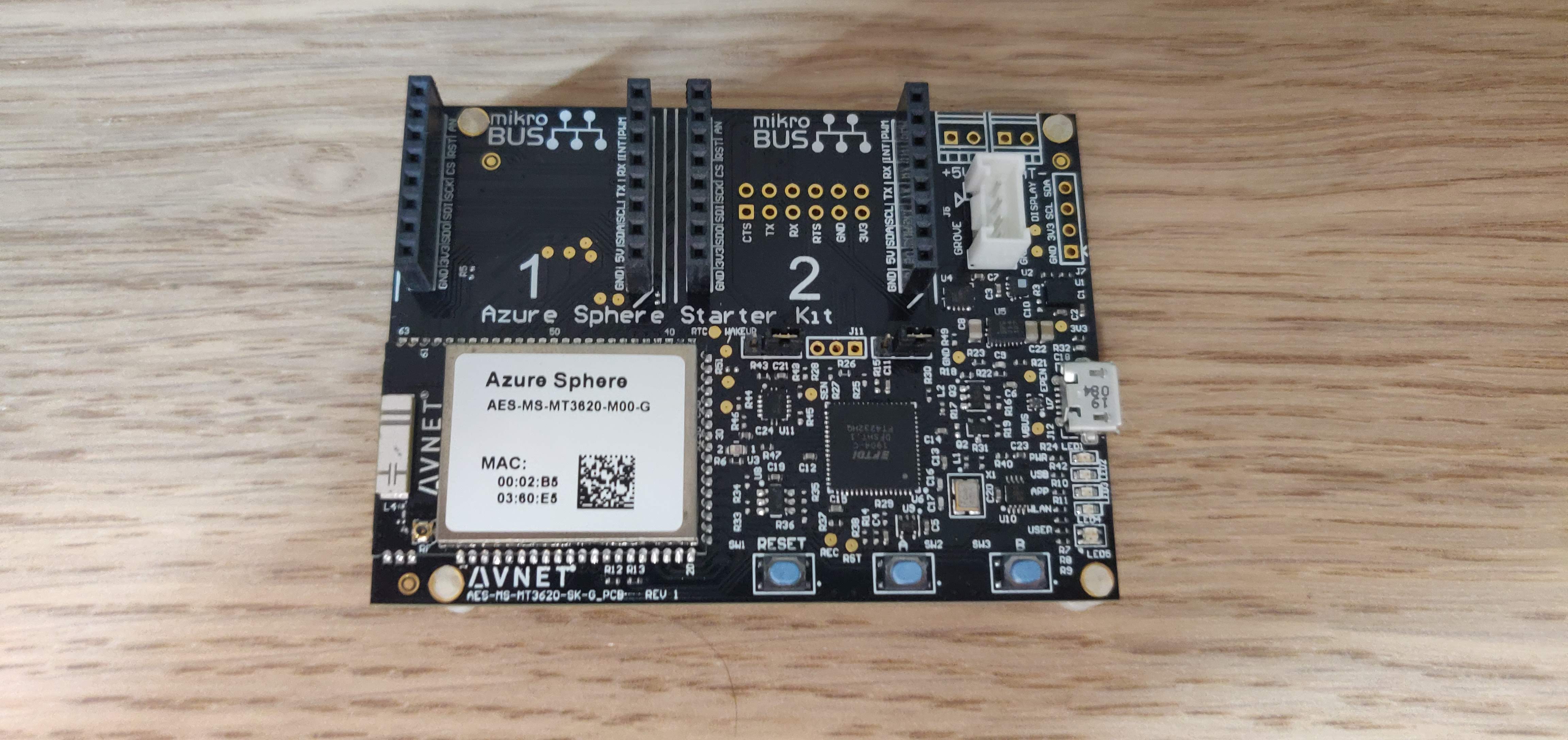
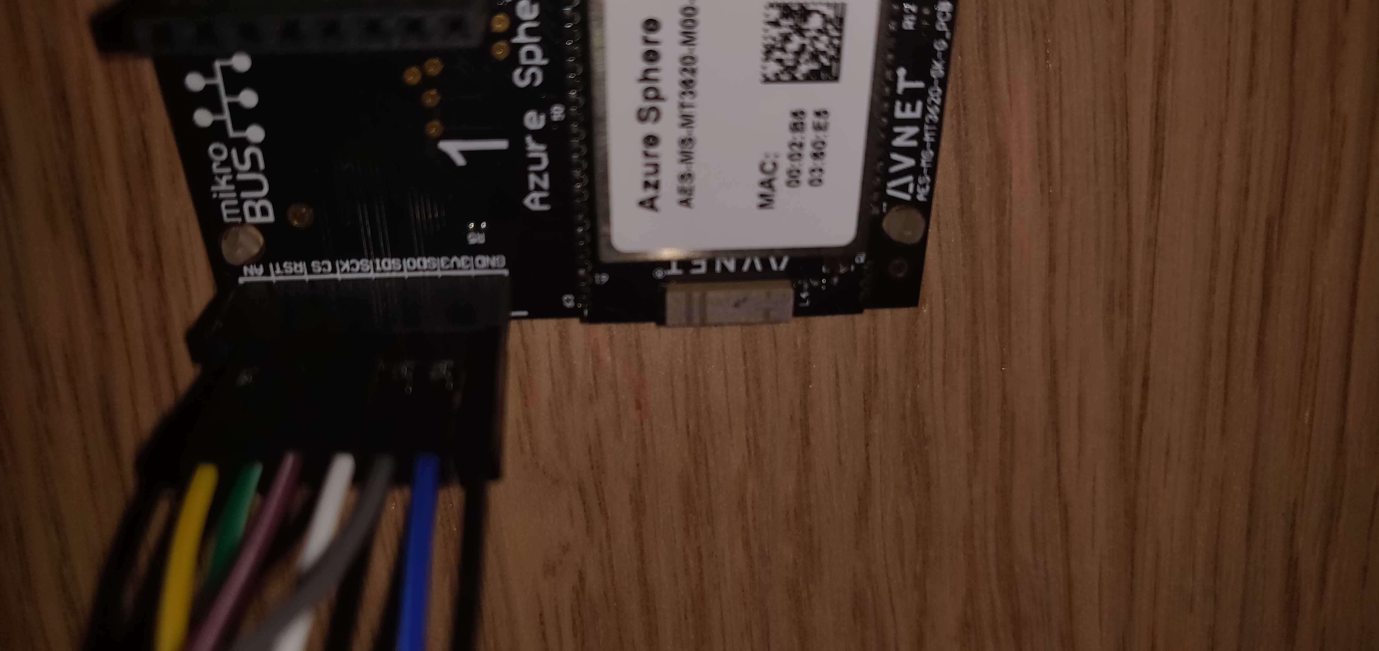
Avnet MT3620
So we talked about the contest, but how does our device actually look like? Well when I received it, it looked like this fresh out of the box:


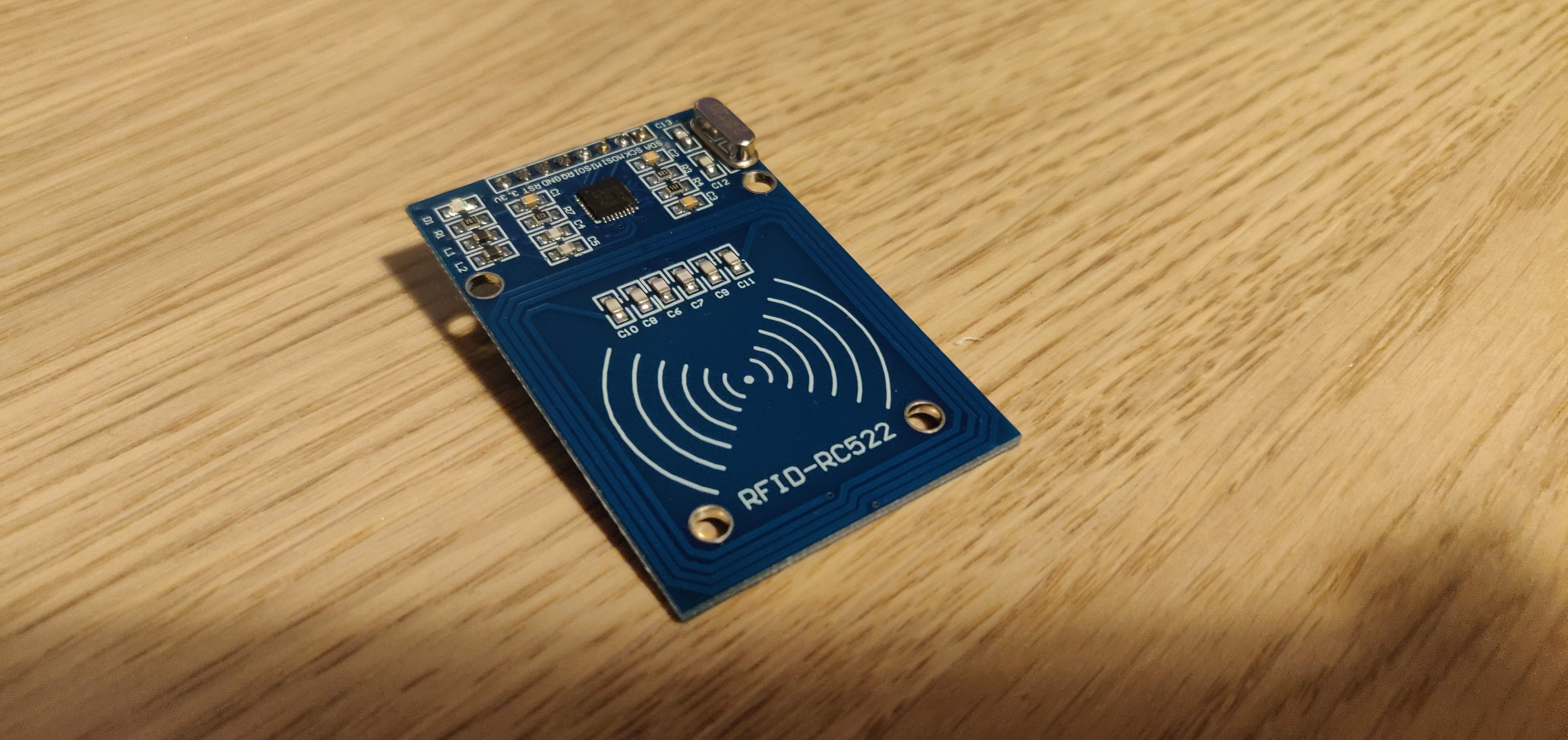
RFID Scanner
We will be utilizing a Mifare RC522 Module RFID Reader as an RFID reader.
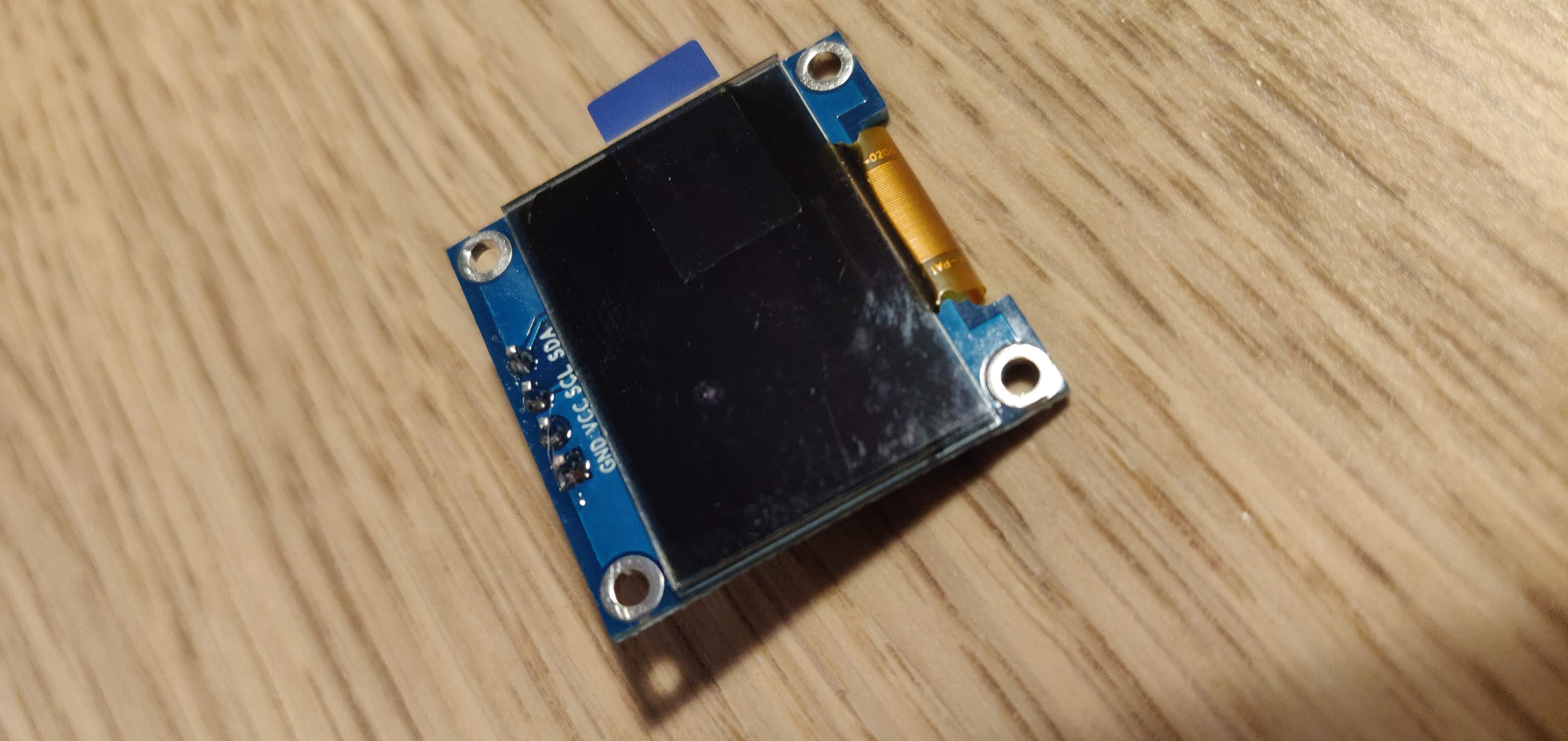
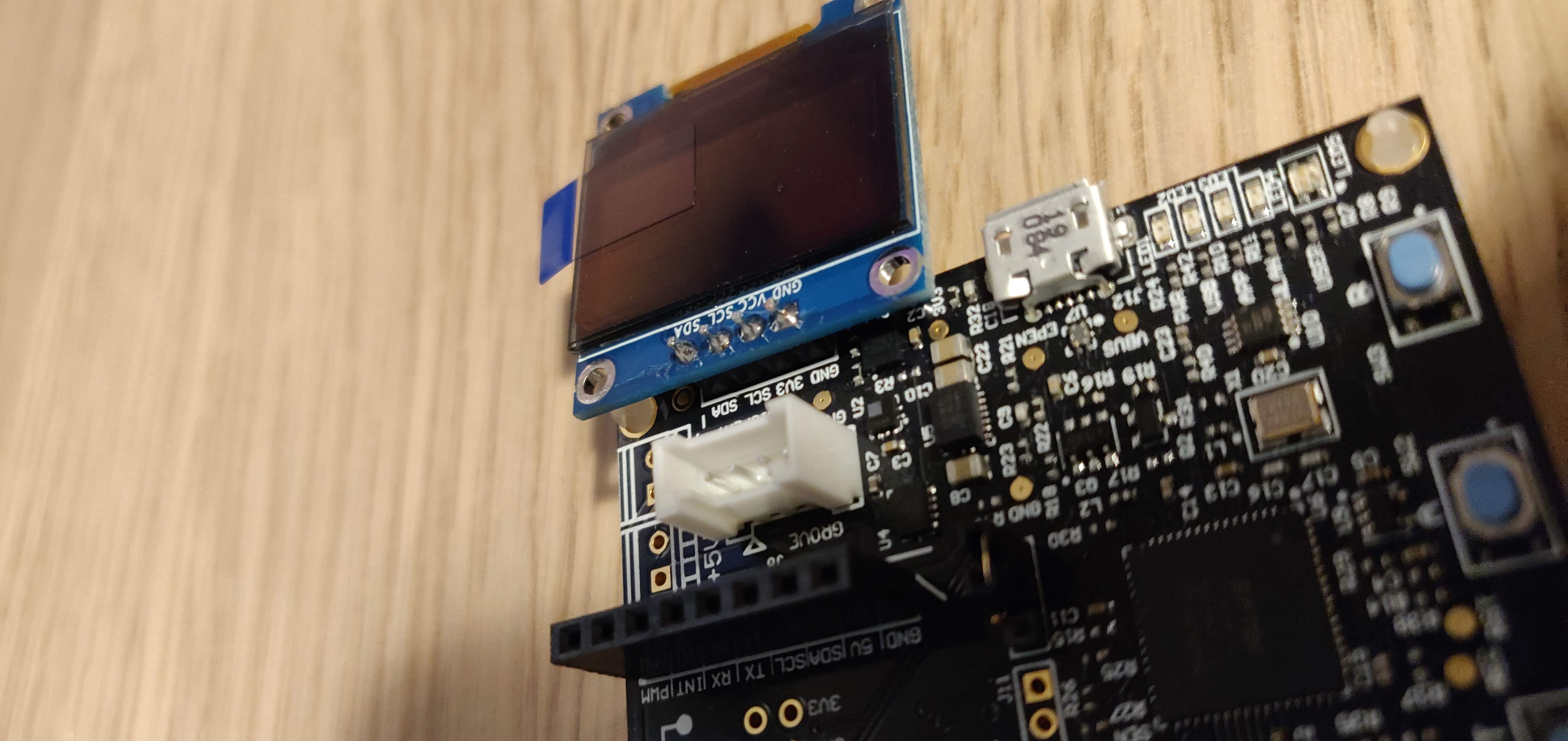
OLED Screen
For our OLED screen I bought an IZOKEE 0.96" I2C IIC SPI Serial 128x64 px display
Basic Concepts - Connecting Hardware
Before we go on and connect our hardware, we should first understand some basic concepts of how hardware gets connected. This is since we want a microcontroller to communicate with small peripheral ICs such as Sensors, ADCs, DACs, …
Serial Peripheral Interface (SPI)
One of these interfaces is a Serial Peripheral Interface (SPI). This is a "synchronous" bus where data is being sent over between a 'master' and a 'slave' and is kept in sync on both sides through the use of a "clock". This interface has 4 logic signals:
- SCLK: Serial Clock (often called SCK)
- Is used to keep both sides in sync, the master generates this.
- MOSI: Master Output Slave Input (often called SDO on master)
- Data being sent from Master -> Slave goes over this data line
- MISO: Master Input Slave Output (often called SDI on master)
- Data being sent from Slave -> Master goes over this data line
- SS: Slave Select (often called CS)
- Select the correct slave and wake it up
- Note: if high, then no slave is active -> active-low configuration
To make this more clearer, here is a diagram to illustrate this:
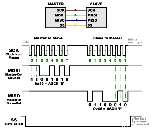
How will SPI send data now? Here a short overview:
- The master sets SCLK (our clock)
- The master selects the slave device (SS) with a logic level 0 on the select line
- During each SPI clock cycle:
- Master sends a bit on the MOSI line and slave reads it
- Slave sends a bit on the MISO line and the master reads it
For our DevKit device, we can find the following about SPI in the datasheet on page 11 and 19.

Click Socket #1:
|Click1 Pin|Module Signal Name|Click1 Pin|Module Signal Name| |-|-|-|-| |AN|GPIO42ADC1|PWM|GPIO0PWM0| |RST|GPIO16|INT|GPIO2PWM2| |CS|GPIO34CSA1CTS1|RX|GPIO28MISO0RXD0SDA0| |SCK|GPIO31SCLK1TX1|TX|GPIO26SCLK0TXD0| |MISO|GPIO33MISO1RX1DATA1|SCL|GPIO37MOSI2RTS2SCL2| |MOSI|GPIO32MOSI1RTS1CLK1|SDA|GPIO38MISO2RXD2SDA2| |+3.3V|3V3|+5V|5V| |GND|GND|GND|GND|
Click Socket #2:
|Click2 Pin|Module Signal Name|Click2 Pin|Module Signal Name| |-|-|-|-| |AN|GPIO43ADC2|PWM|GPIO1PWM1| |RST|GPIO17|INT|GPIO2PWM2| |CS|GPIO35CSB0|RX|GPIO28MISO0RXD0SDA0| |SCK|GPIO31SCLK1TX1|TX|GPIO26SCLK0TXD0| |MISO|GPIO33MISO1RX1DATA1|SCL|GPIO37MOSI2RTS2SCL2| |MOSI|GPIO32MOSI1RTS1CLK1|SDA|GPIO38MISO2RXD2_SDA2| |+3.3V|3V3|+5V|5V| |GND|GND|GND|GND|
Connecting Azure Sphere and our Hardware
Activate network and Claim the device
First off when we receive a new Azure Sphere device is to activate its network and claim it.
Note: Special at Azure Sphere is that these devices always have a radio built in, enabling network connectivity.
Activating Network
# Show the status of the WiFi connection
azsphere device wifi show-status

# Connect the device to WiFi
azsphere device wifi add --ssid <yourSSID> --key <yourKey>
Claiming the device
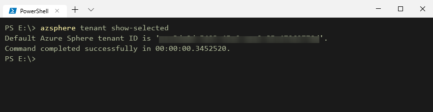
# Login to Azure and see the tenants
azsphere login

# Select the tenant (XavierAzureSphereTenant)
azsphere tenant select -i aca3da0d-5493-45e6-aea2-85c47962770d

# Claim the device
azsphere device claim
Enabling debugging on our Azure Sphere
Before we can now get started and deploy code on our Azure Sphere, we have to configure it so it allows sideloading. For that just execute the command azsphere device prep-debug which will configure the device and reboot it so we are ready to go!
Connecting the RFID Scanner
Since we learned what the SPI interface is, we can now connect our RFID scanner. For that just connect the corresponding pins on the RFID scanner with the ones on our devkit as shown here. For this we look at the SPI details in the datasheet on page 9. Here we find the following:
|PIN|UART(input)|SPI (output)|I2C-bus (I/O)| |-|-|-|-| |SDA|RX|NSS|SDA| |I2C|0|0|1| |EA|0|1|EA| |D7|TX|MISO|SCL| |D6|MX|MOSI|ADR0| |D5|DTRQ|SCK|ADR1| |D4|-|-|ADR2| |D3|-|-|ADR3| |D2|-|-|ADR4| |D1|-|-|ADR5|
Where we see that for SPI we need to utilize NSS, MISO, MOSI, SCK on our development board, which refer to SDA, MISO, MOSI, SCK on the RFID scanner.
Once connected, we will have this:

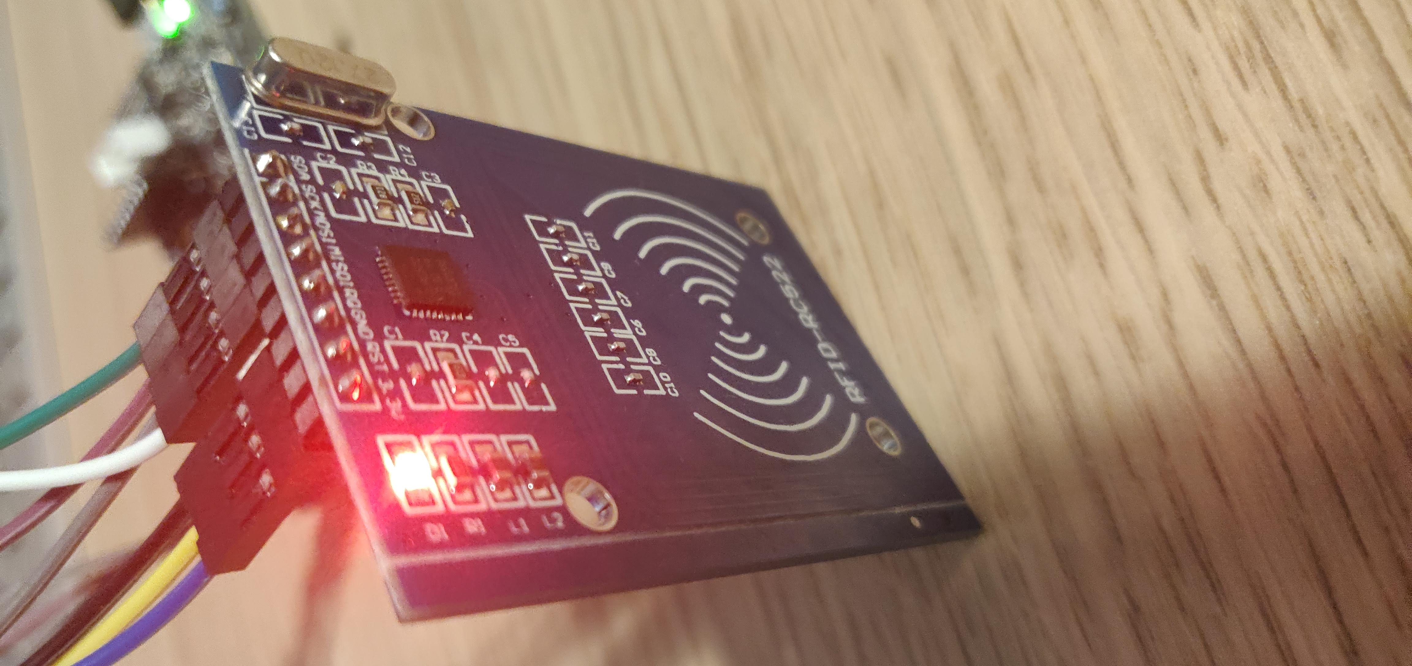
Drawing this out, we will get:
RFID|DEVICE|COLOR -|-|- SDA|CS|GREEN SCK|SCK|PURPLE MOSI|SDO|GREY MISO|SDI|WHITE RQ|-|-| GND|GND|BLACK RST|RST|YELLOW 3.3V|3V3|BLUE
Connecting the OLED screen
The OLED screen is quite straightforward for our project, seeing that it's the one as shown on page 22 in the datasheet. It has the following pin connectors:
|Grove Pin #|Signal Name|Signal Name| |-|-|-| |1|GND|GND| |2|3V3|3V3| |3|SCL|GPIO37MOSI2RTS2SCL2| |4|SDA|GPIO38MISO2RXD2SDA2|
Azure
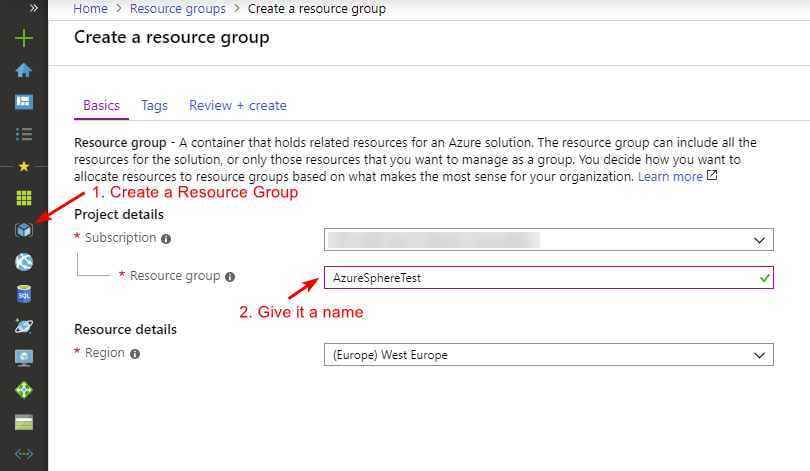
To be able to connect our device and control it, we will work with Azure. In Azure we always start off with creating a resource group when we want to test something.
Azure IoT Hub
Connecting devices to cloud is done through IoT Hub, this is a service that allows us to manage our devices as well as receive / send data from / to them. For our demonstration we will choose the S1 tier.
Note: the F1 tier will also be sufficient but has a smaller limit of messages / day

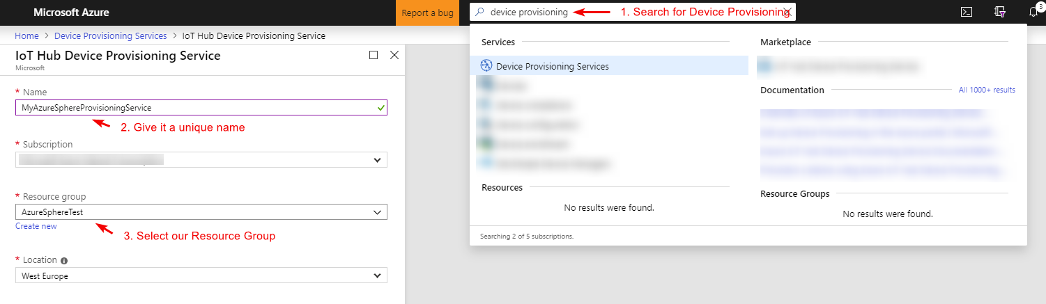
Azure Device Provisioning
Now we have an IoT Hub and an IoT Edge device, how do we actually connect this device to IoT Hub? One way would be to go through the portal and create our device manually. This is however not something we want to do seeing the manual work involved, wouldn't it be better if we could let our device handle all of this automatically?
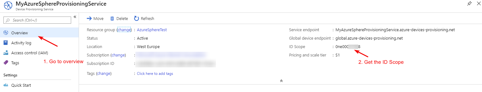
For that we have the Azure Device Provisioning Service, which will automatically provision our IoT device once it gets connected to the IoT Hub (this through a Enrollment list, but more later on that).
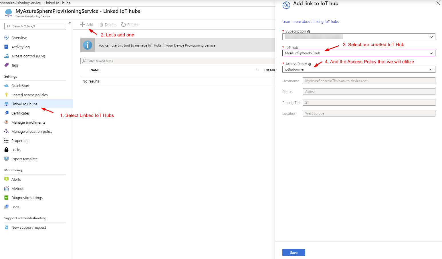
Once our Device Provisioning Service (DPS) has been set up, we can link our IoT Hub to it:
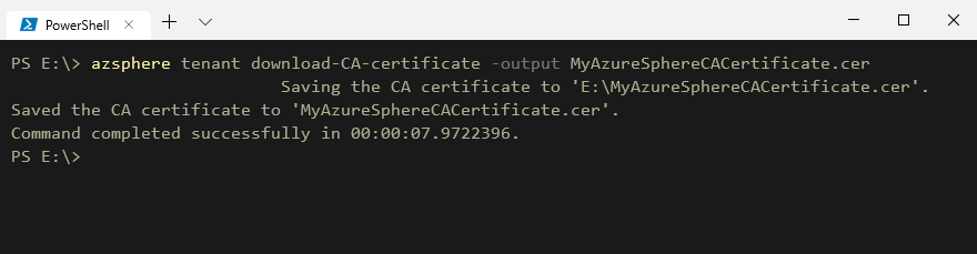
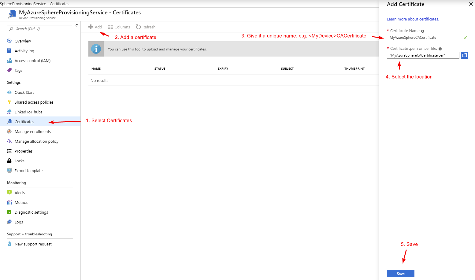
The last thing we now have to do is add our device to the enrollment list, here we have the choice to add our devices through Certificates our symmetric keys. Seeing the nature of IoT Edge devices and that we want to let them be as secure as possible, we will thus utilize a Certificate for this. First we will get our device its CA certificate by running the command azsphere tenant download-CA-certificate -output MyAzureSphereCACertificate.cer, whereafter we will add it to our DPS service and create an enrollment for it. See the pictures below on how this will look:
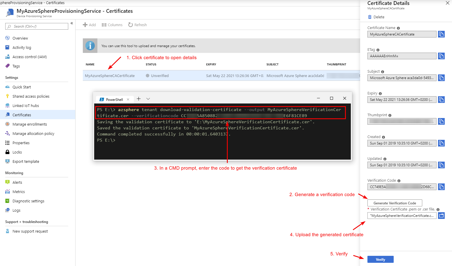
Now since we uploaded a certificate we need to verify that it's the correct certificate, for this get the code on the detail pane and verify it with azsphere tenant download-validation-certificate --output MyAzureSphereVerificationCertificate.cer --verificationcode <code>. Whereafter we upload this to the portal.
Last but not least we are now able to create an Enrollment Group where this device will be part of.
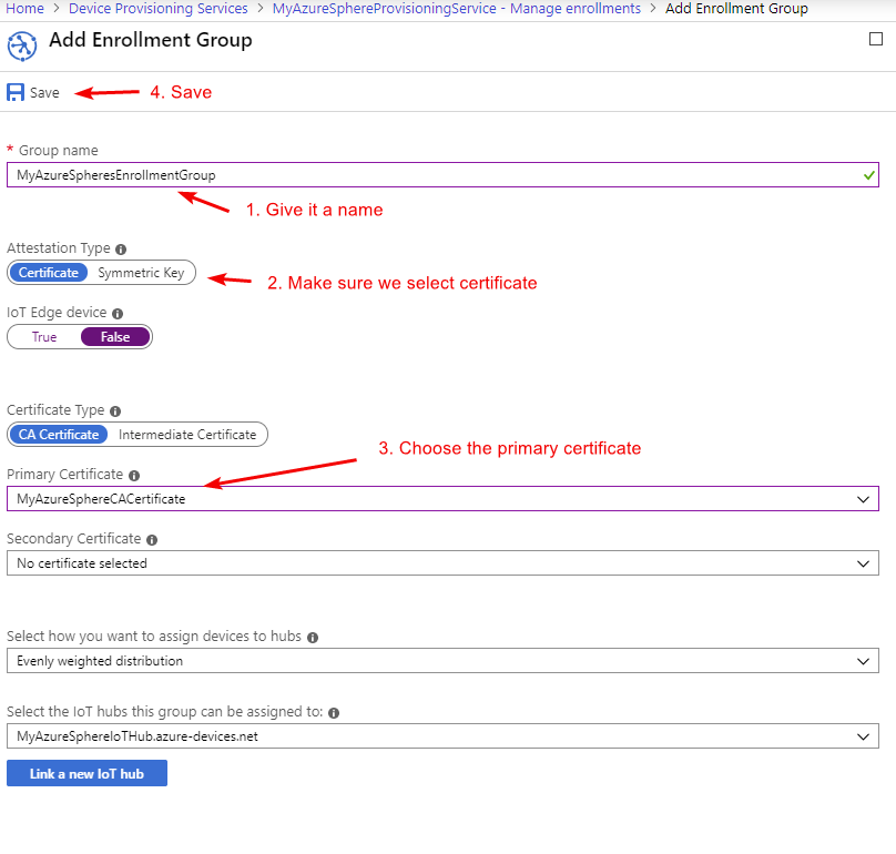
Now when our device connects, it will be automatically added.
Coding our Project
Before we start coding, important to note is as well that the Azure Sphere SDK includes a set of Application Libraries (AppLibs) that make it easy for us to develop an Azure Sphere applications. For more information, check the Azure Documentation
Code Setup
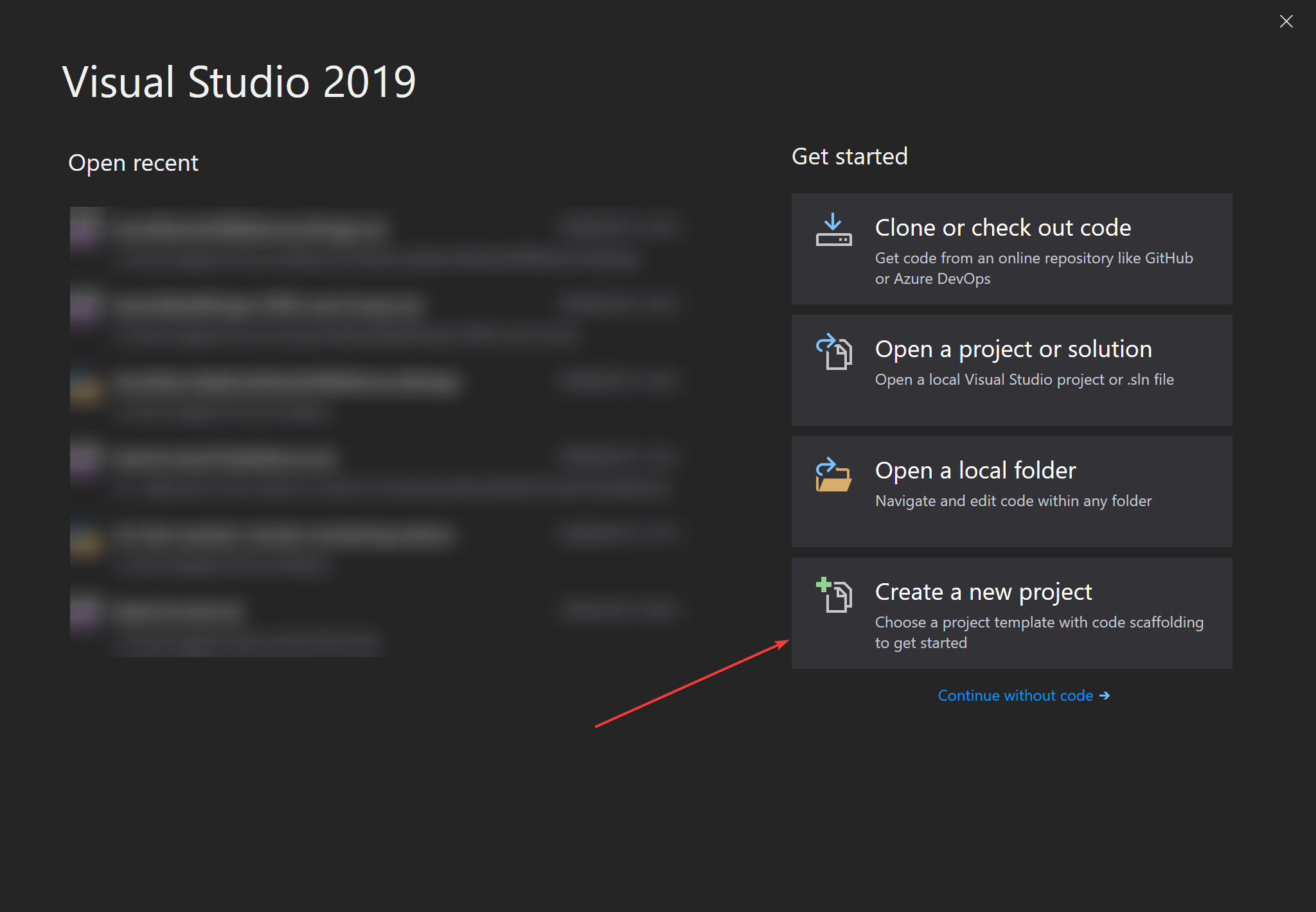
Now, since we connected our hardware, let's get started with coding our project. For that start off with creating a solution in Visual Studio as follows:
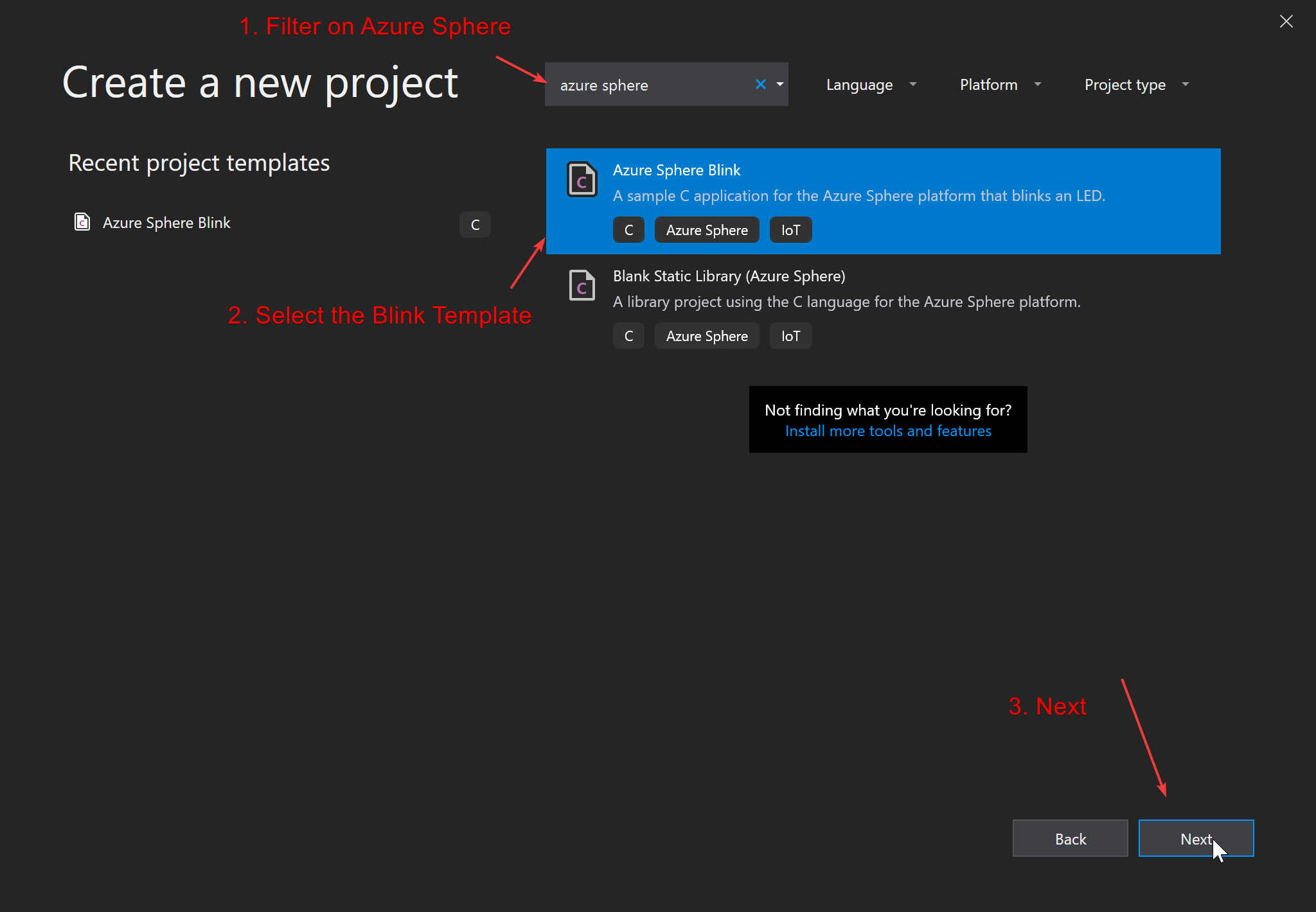
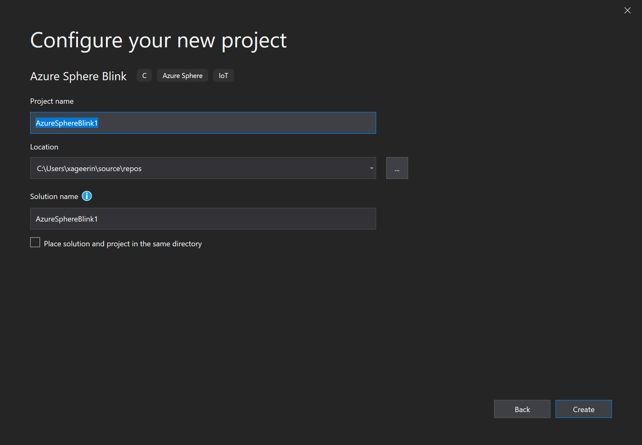
Since we now have a project, we now want to correct some properties:
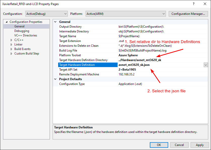
- Change the SDK to the BETA version. For this, follow this guide and select the "2+Beta1905" version.
- We want to set the correct Hardware Target reference to be utilized in our app manifest. For this, we will copy over the Hardware folder from the Azure Sphere Samples to our project root (where our solution is sitting) as shown here.
- We want to access easy pin definitions as defined in step 2. For that, find the respective header files in the Hardware folder from step 2 and include them into your project. (for our Avnet development board, we thus have to include
mt3620.h,avnet_mt3620_aesms.handavnet_mt3620_sk.h).
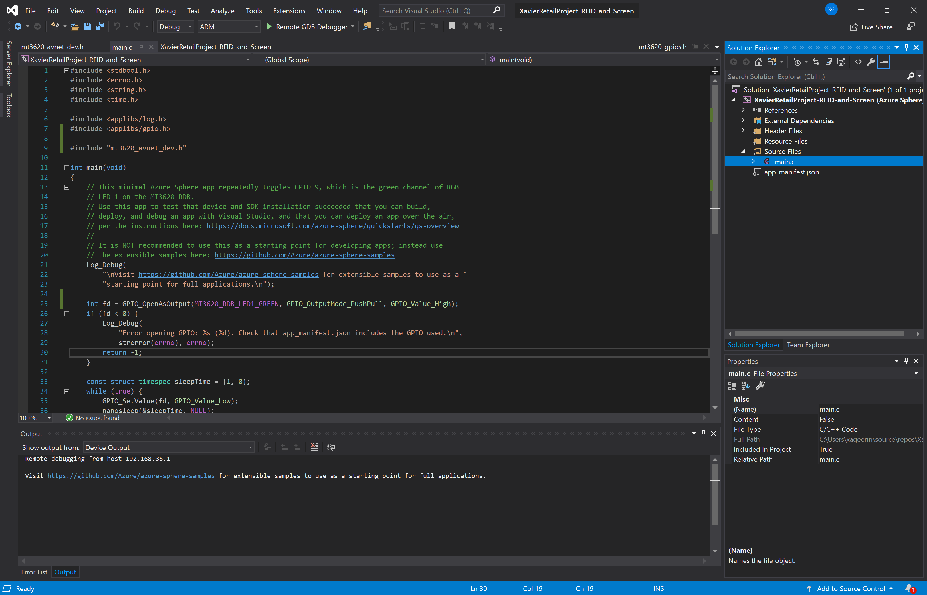
Hello World - OLED Screen
The easiest code samples always start with a Hello World sample, so let's create one for the OLED display.
Note: Seeing that the scope of this post is to actually make a fully E2E working project, we are going to skip through this quite quickly, but feel free to find the source code in the GitHub repository.
Luckily for us, Avnet already used this type of OLED screen and working source code is available. Therefor we copy the following files:
oled.holed.csd1306.hsd1306.cfont.h
We then change some parts to let it suit or needs (as well as strip unneeded code that access the accelerometer and other sensors) and add this in our main.c code:
// OUR IMPORTS
int main(int argc, char* argv[])
{
// Start the OLED Screen
if (oled_init())
{
Log_Debug("OLED not found!\n");
}
else
{
Log_Debug("OLED found!\n");
}
// Clear the buffer
oled_buffer_clear();
// Draw the strings
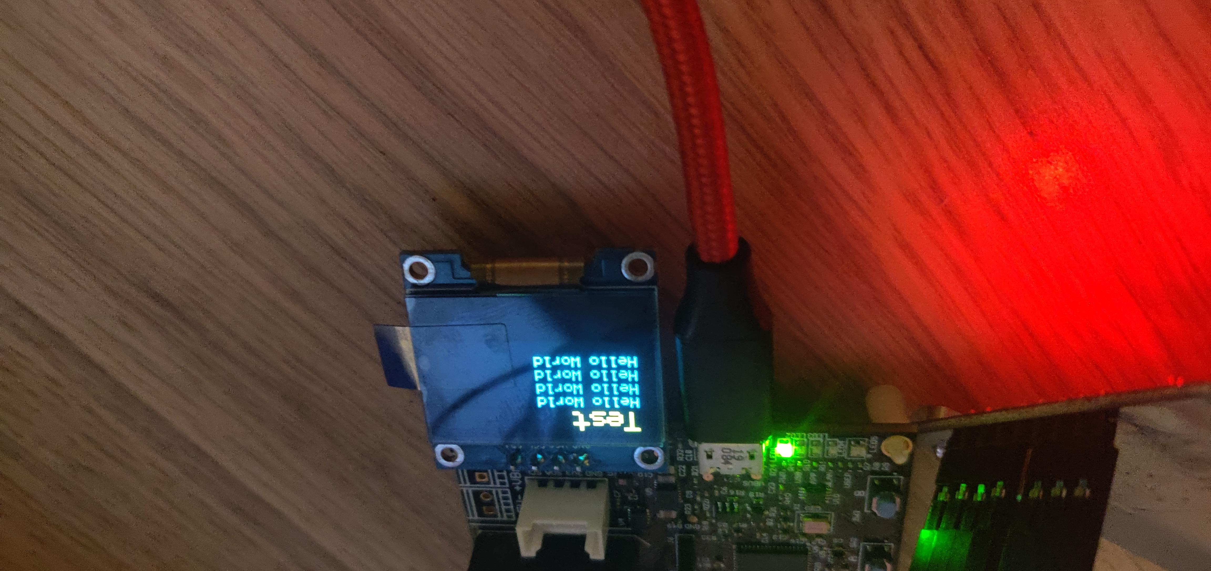
sd1306_draw_string(0, 0, "Test", FONT_SIZE_TITLE, white_pixel);
sd1306_draw_string(OLED_LINE_1_X, OLED_LINE_1_Y, "Hello World", FONT_SIZE_LINE, white_pixel);
sd1306_draw_string(OLED_LINE_2_X, OLED_LINE_2_Y, "Hello World", FONT_SIZE_LINE, white_pixel);
sd1306_draw_string(OLED_LINE_3_X, OLED_LINE_3_Y, "Hello World", FONT_SIZE_LINE, white_pixel);
sd1306_draw_string(OLED_LINE_4_X, OLED_LINE_4_Y, "Hello World", FONT_SIZE_LINE, white_pixel);
// Send the buffer to OLED RAM
sd1306_refresh();
return 0;
}
We can now see Hello World being printed on the screen:
Hello World - RFID Scanner
As a Hello World for our RFID scanner, we will be reading the version of our RFID scanner.
Note: this is not an easy feat since there is no library in existance for the RFID scanner that works with the Azure Sphere chipset
For this we will rework this library and bake in our chip support through the SPI applibs .
Note: Seeing that the scope of this post is to actually make a fully E2E working project, we are going to skip through this quite quickly, but feel free to find the source code in the GitHub repository.
In short, we will adapt the read and write methods to utilize our Azure Sphere SPI interface so that they look like this:
void mfrc522_write(uint8_t reg, uint8_t data)
{
    const size_t transferCount = 1;
    SPIMaster_Transfer transfer;

    int result = SPIMaster_InitTransfers(&transfer, transferCount);
    if (result != 0) {
        return;
    }

    //const uint8_t command[] = { (reg << 1) & 0x7E, data };
    const uint8_t command[] = { (reg << 1) & 0x7E, data };
    transfer.flags = SPI_TransferFlags_Write;
    transfer.writeData = command;
    transfer.length = sizeof(command);

    ssize_t transferredBytes = SPIMaster_TransferSequential(spiFd, &transfer, transferCount);

    if (!CheckTransferSize("SPIMaster_TransferSequential (CTRL3_C)", transfer.length, transferredBytes)) {
        Log_Debug("Transfer size is not correct");
        return;
    }
}

uint8_t mfrc522_read(uint8_t reg)
{
    uint8_t readDataResult;
    //uint8_t readCmd = ((reg << 1) & 0x7E) | 0x80; // Set bit 7 indicating it's a read command -> 0x80
    uint8_t readCmd = ((reg << 1) & 0x7E | 0x80); // Set bit 7 indicating it's a read command -> 0x80
    ssize_t transferredBytes = SPIMaster_WriteThenRead(spiFd, &readCmd, sizeof(readCmd), &readDataResult, sizeof(readDataResult));

    if (!CheckTransferSize("SPIMaster_WriteThenRead (CTRL3_C)", sizeof(readCmd) + sizeof(readDataResult), transferredBytes)) {
        Log_Debug("Transfer size is not correct");
        return -1;
    }

    Log_Debug("INFO: READ=0x%02x (SPIMaster_WriteThenRead)\n", readDataResult);

    return readDataResult;
}
We can then adapt our main.c code to initialize the RFC library and start reading the version:
// INCLUDES

void delay(int s)
{
    sleep(s);
}

int main(void)
{
    Log_Debug("IPC RFID RC522 Application Starting\n");

    // Start the RFID Scanner
    if (mfrc522_init())
    {
        Log_Debug("RFID Scanner not found!\n");
    }
    else
    {
        Log_Debug("RFID Scanner found!\n");
        return -1;
    }

    // Look for a card
    while (1)
    {
        Log_Debug("Trying to get version\n");
        // Check version of the reader
        // Can be 0x91 for 1.0 or 0x92 for 2.0 -> https://www.nxp.com/docs/en/data-sheet/MFRC522.pdf (p66 - VersionReg register)
        uint8_t byte = mfrc522_read(VersionReg);

        Log_Debug("Detected version %d (Hex: %x)\n", byte, byte);

        delay(5);
    }

    return 0;
}
Hello World - Azure
For our Azure connectivity we want to do something very basic, here we just want to demonstrate:
- Sending data to cloud
- Receiving data from cloud
Therefor we will create an application that is going to send the status of the green LED light every 10 seconds and we will utilize a Device Twin to change the status of this LED.
Configuring our App Manifest
The first thing we will do is to configure our app_manifest.json:
- Add the Device Provisioning Service Scope ID to the
CmdArgsblock (e.g."CmdArgs: [ "<YourScopeID>" ]) - Add the tenant id to the
DeviceAuthenticationkey (e.g."DeviceAuthentication": "00000000-0000-0000-0000-000000000000") - Set the
AllowedConnectionskey to allow the device provisioning service and your IoTHub connection string (e.g."AllowedConnections": [ "global.azure-devices-provisioning.net", "MyAzureSphereIoTHub.azure-devices.net" ]) - Seeing that we will let the GREEN LED blink, we need to enable Gpio pin 9 (e.g.
"Gpio": [ 9 ])
Writing our Code
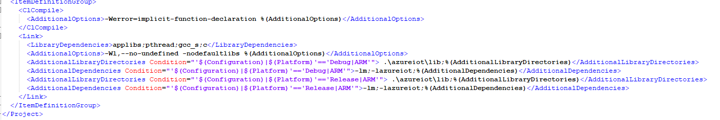
First we configure our project by opening the .vcxproj in a text editor and adding the following in the <Link> tags:
<AdditionalLibraryDirectories Condition="'$(Configuration)|$(Platform)'=='Debug|ARM'"> .\azureiot\lib;%(AdditionalLibraryDirectories)</AdditionalLibraryDirectories>
<AdditionalDependencies Condition="'$(Configuration)|$(Platform)'=='Debug|ARM'">-lm;-lazureiot;%(AdditionalDependencies)</AdditionalDependencies>
<AdditionalLibraryDirectories Condition="'$(Configuration)|$(Platform)'=='Release|ARM'"> .\azureiot\lib;%(AdditionalLibraryDirectories)</AdditionalLibraryDirectories>
<AdditionalDependencies Condition="'$(Configuration)|$(Platform)'=='Release|ARM'">-lm;-lazureiot;%(AdditionalDependencies)</AdditionalDependencies>
Making it look like this:
Luckily for us, the azureiot files are included through the Azure Sphere SDK installation (typically in C:\Program Files (x86)\Microsoft Azure Sphere SDK\Sysroots\2+Beta1905\usr\include\azureiot\), so we can have the following includes defined:
// Azure IoT SDK
#include <azureiot/iothub_client_core_common.h>
#include <azureiot/iothub_device_client_ll.h>
#include <azureiot/iothub_client_options.h>
#include <azureiot/iothubtransportmqtt.h>
#include <azureiot/iothub.h>
#include <azureiot/azure_sphere_provisioning.h>
For the rest of our code, we will be utilizing one of the Azure Sphere examples that we adapt to only include the LED light and Twin functionality. When we then run this, we see:
Remote debugging from host 192.168.35.1
Application Starting
Setting Azure Scope ID 0ne000777D8
Opening GREEN LED as output
[Azure IoT] Using HSM cert at /run/daa/aca3da0d-5493-45e6-aea2-85c47962770d
[IoTHub][INFO] IoTHubDeviceClient_LL_CreateWithAzureSphereDeviceAuthProvisioning returned 'AZURE_SPHERE_PROV_RESULT_OK'.
[IoTHub][INFO] Configuring Device Twin Callback and Connection Status Callback
[IoTHub][INFO] Sending IoT Hub Message: { "Test": "Hello World" }
[IoTHub][INFO] IoTHubClient accepted the message for delivery
[IoTHub][INFO] Received IoT Twin Update from IoT Hub
[IoTHub][INFO] Changing Status LED to true
[IoTHub][INFO] Reported state for 'MyGreenLED' to value 'true'.
[IoTHub][INFO] Sending IoT Hub Message: { "Test": "Hello World" }
[IoTHub][INFO] IoTHubClient accepted the message for delivery
[IoTHub][INFO] Message received by IoT Hub. Result is: 0
Note: Initially I gotIOTHUB_CLIENT_CONNECTION_NO_NETWORK, which was because I forgot to configure my IoT Hub endpoint in theapp_manifest.jsonfile under"AllowedConnections".
For the full code, please see the GitHub repository.
RFID Scanner + OLED Screen for Serial Reading
The next step we will now do before connecting it all to cloud is to be able to read the tags from our RFID Tags and display their serial number. Seeing the 2 hello world examples this should be trivial to do now. Therefor we copy everything from the 2 hello world projects into 1 project and use the following main.c file that will display some information in-between and will read and display the serial every time the tag is presented.
main.c
// INCLUDES...

// DECLARE FUNCTIONS...

void delay(int s)
{
    sleep(s);
}

uint8_t InitPeripherals()
{
    Log_Debug("[OLED] Initializing\n");
    if (oled_init())
    {
        Log_Debug("OLED not found!\n");
    }
    else
    {
        Log_Debug("OLED found!\n");
    }

    Log_Debug("[MFRC522] Initializing\n");
    if (mfrc522_init())
    {
        Log_Debug("RFID Scanner not found!\n");
    }
    else
    {
        Log_Debug("RFID Scanner found!\n");
        return -1;
    }
}

int main(void)
{
    int res = InitPeripherals();
    if (res < 0) {
        Log_Debug("Error, exiting!\n");
        return -1;
    }

    oled_template_waiting_for_rfc();

    // Get Card Version
    Log_Debug("Trying to get version\n"); // 0x91 = 1.0, 0x92 = 0.2 -> https://www.nxp.com/docs/en/data-sheet/MFRC522.pdf (p66 - VersionReg register)
    uint8_t readerVersion = mfrc522_read(VersionReg);

    Log_Debug("Detected version %d (Hex: %x)\n", readerVersion, readerVersion);
    oled_template_waiting_for_rfc_with_version(readerVersion);

    // Prepare for reading tags
    uint8_t byte;
    byte = mfrc522_read(ComIEnReg);
    mfrc522_write(ComIEnReg, byte | 0x20);
    byte = mfrc522_read(DivIEnReg);
    mfrc522_write(DivIEnReg, byte | 0x80);

    delay(2);

    // Look for a card
    // Commands: https://www.nxp.com/docs/en/data-sheet/MFRC522.pdf P36
    uint8_t str[MAX_LEN];

    while (1)
    {
        byte = mfrc522_request(PICC_REQALL, str); // Find all the cards antenna area

        if (byte == CARD_FOUND)
        {
            Log_Debug("[MFRC522] Found a card: %x\n", byte);

            byte = mfrc522_get_card_serial(str);

            if (byte == CARD_FOUND)
            {
                for (byte = 0; byte < 8; byte++)
                {
                    Log_Debug("[MFRC522] Dumping: %x\n", str[byte]);
                }

                // Convert the byte array to a string of bytes
                char hexstr[8];
                btox(hexstr, str, 8);
                hexstr[8] = 0;
                Log_Debug("%s\n", hexstr);
                oled_template_show_serial(hexstr);

                delay(3);
            }
            else
            {
                Log_Debug("[MFRC522] Error while reading card\n");
            }
        }

        delay(1);
    }

    // Todo: close SPI here

    return 0;
}

void btox(char* xp, const char* bb, int n)
{
    const char xx[] = "0123456789ABCDEF";
    while (--n >= 0) xp[n] = xx[(bb[n >> 1] >> ((1 - (n & 1)) << 2)) & 0xF];
}

void oled_template_waiting_for_rfc(void)
{
    // Clear the buffer
    oled_buffer_clear();

    // Draw the strings
    sd1306_draw_string(0, 0, "Information", FONT_SIZE_TITLE, white_pixel);
    sd1306_draw_string(OLED_LINE_1_X, OLED_LINE_1_Y, "Waiting for tag to", FONT_SIZE_LINE, white_pixel);
    sd1306_draw_string(OLED_LINE_2_X, OLED_LINE_2_Y, "be detected", FONT_SIZE_LINE, white_pixel);

    // Send the buffer to OLED RAM
    sd1306_refresh();
}

void oled_template_waiting_for_rfc_with_version(uint8_t version)
{
    // Clear the buffer
    oled_buffer_clear();

    // Draw the strings
    sd1306_draw_string(0, 0, "Information", FONT_SIZE_TITLE, white_pixel);
    sd1306_draw_string(OLED_LINE_1_X, OLED_LINE_1_Y, "Waiting for tag to", FONT_SIZE_LINE, white_pixel);
    sd1306_draw_string(OLED_LINE_2_X, OLED_LINE_2_Y, "be detected", FONT_SIZE_LINE, white_pixel);

    char versionBuffer[20];
    sprintf(versionBuffer, "MIFARE Version = %x", version);
    sd1306_draw_string(OLED_LINE_3_X, OLED_LINE_3_Y, versionBuffer, FONT_SIZE_LINE, white_pixel);

    // Send the buffer to OLED RAM
    sd1306_refresh();
}

void oled_template_show_serial(char* serial)
{
    // Clear the buffer
    oled_buffer_clear();

    // Draw the strings
    sd1306_draw_string(0, 0, "Information", FONT_SIZE_TITLE, white_pixel);
    sd1306_draw_string(OLED_LINE_1_X, OLED_LINE_1_Y, "Serial:", FONT_SIZE_LINE, white_pixel);
    sd1306_draw_string(OLED_LINE_2_X, OLED_LINE_2_Y, serial, FONT_SIZE_LINE, white_pixel);

    // Send the buffer to OLED RAM
    sd1306_refresh();
}
Putting it all together - RFID + OLED + Azure
Since we have the basic functionality done now, we want to put it all together. When we scan a RFID tag, we look in a local array for the price information and display this on screen. By utilizing Azure we will now add the functionality to update this price information through Device Twins as well as send an event to IoTHub stating our scanned tag and price identified.
Doing this will require a few things that we will do (not displayed here for shortness reasons, see source code):
- Add a custom event handler for the RFID and merge the code in there
- Add OLED display methods for displaying the price
- Including a MAP datastructure that we can utilize to hold our price for the tags
- Updating the Azure Twin so that we are able to update the price for the tags through the Device Twin (cloud to device)
Once we adapted our code to incorporate this, we can then see something like this when testing (added comments for clarity)
Remote debugging from host 192.168.35.1
# 1. Initializing the application
[Application][INFO] Starting
[Application][INFO] Setting Azure Scope ID <MASKED>
[OLED][INFO] Initializing
[OLED][INFO] OLED found!
[MFRC522][INFO] Initializing
[MFRC522][SPI][INFO] Initializing
[MFRC522][SPI][INFO] Opened SPI Interface
[MFRC522][SPI][INFO] BusSpeed = 4000000
[MFRC522][SPI][INFO] SPIMode = 1
[MFRC522][SPI][INFO] BitOrder = SPI_BitOrder_MsbFirst
[MFRC522][SPI][INFO] FD Set on 4
[MFRC522][SPI][INFO] Initialized
[MFRC522][INFO] RFID Scanner found!
[ePoll][INFO] Initializing
# 2. Detecting the scanner version
[MFRC522][INFO] Trying to get version
[MFRC522][INFO] Detected version 146 (Hex: 92)
[MFRC522][INFO] Waiting for IoTHub Connection
# ...
[MFRC522][INFO] Waiting for IoTHub Connection
# 3. Configuring our IoT Hub Connection
[Azure IoT] Using HSM cert at /run/daa/<MASKED>
[IoTHub][INFO] IoTHubDeviceClient_LL_CreateWithAzureSphereDeviceAuthProvisioning returned 'AZURE_SPHERE_PROV_RESULT_OK'.
[IoTHub][INFO] Configuring Device Twin Callback and Connection Status Callback
[IoTHub][INFO] IoT Hub Authenticated: IOTHUB_CLIENT_CONNECTION_OK
# 4. Handling the Azure Device Twin Update
[IoTHub][INFO] Received IoT Twin Update from IoT Hub
[IoTHub][Twin][INFO] Updating PriceMap
[IoTHub][Twin][INFO] 8804399D -> Zombie: $15.50
[IoTHub][Twin][INFO] Updating price for 7908C820 to Normal: $14.11
[IoTHub][ERROR] Reported state for '7908C820' to value 'Normal: $14.11'.
[IoTHub][Twin][INFO] 88041B9D -> Skeleton: $20.00
[IoTHub][INFO] Device Twin reported properties update result: HTTP status code 400
# 5. Reading our card and displaying it to the screen
[MFRC522][INFO] Found a card: 1
[MFRC522][INFO] Dumping: 79
[MFRC522][INFO] Dumping: 8
[MFRC522][INFO] Dumping: c8
[MFRC522][INFO] Dumping: 20
[MFRC522][INFO] Dumping: 99
[MFRC522][INFO] Dumping: 0
[MFRC522][INFO] Dumping: 0
[MFRC522][INFO] Dumping: 0
[MFRC522][INFO] Serial: 7908C820
[MAP][INFO] Map Price: Normal: $14.11
Testing
When we test this in real life, we will see something as shown in the videos below. What we see here is the scanning of tags on the device, executing a twin update and seeing the updated price on the device. Note that we also show the event data being sent to Azure through a consumer. This consumer is quite basic and looks like this:
const config = require('./config');

const { Client } = require('azure-event-hubs');
const connectionString = "<YOUR_IOTHUB_CONNECTION_STRING>";
const consumerGroup = '$Default';

const printError = (err) => {
  console.log(err.message);
};

const client = Client.fromConnectionString(connectionString);
client.open()
.then(client.getPartitionIds.bind(client))
.then((partitionIds) => {
  return partitionIds.map((partitionId) => {
    client.createReceiver(consumerGroup, partitionId, { 'startAfterTime': Date.now() })
    .then((receiver) => {
      console.log(`[Receiver] Created partition receiver: [${partitionId}] for consumerGroup [${consumerGroup}]`);
      receiver.on('errorReceived', printError);
      receiver.on('message', (message) => {
        console.log(`[Receiver][${consumerGroup}][${partitionId}] Message received: ${JSON.stringify(message.body).toString()}`);
      });
    })
  })
})
.catch(printError);
screencast
<video width="960" height="540" controls autoplay>
  <source src="./mp4">
Your browser does not support the video tag.
</video>
device
<video width="640" height="480" controls autoplay>
  <source src="./mp4">
Your browser does not support the video tag.
</video>
To see the full code that was used to create this example, feel free to check this repository: https://github.com/Xaviergeerinck/PublicProjects/tree/master/C/AzureSphere-Avnet-E2E-Project.
Comments ()